My second version of the amplifier was a result from a discussion thread in a swedish hifi forum where we tried to reach a conclusion on a design other members could build. HFTA is an acronym for Hifi Forum Tube Amplifier. It was ready for demonstration at a Hifi DIY meeting in 2005 and was a success.
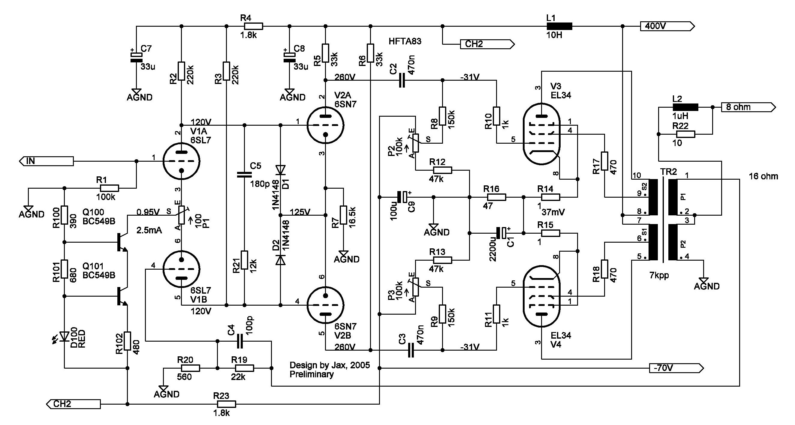
I scrapped my previous design to reuse in this. I changed the L63 tube for 6SL7 configured as an LTP with a constant current sink as tail. An advantage is that I got rid of a cathode decoupling capacitor. The former phase splitter is changed to a pure LTP driver stage. Phase splitting is done in the input tube in a way resembling an operational amplifier. Input goes to the grid of one of the input triodes and the feedback to the grid of the other.
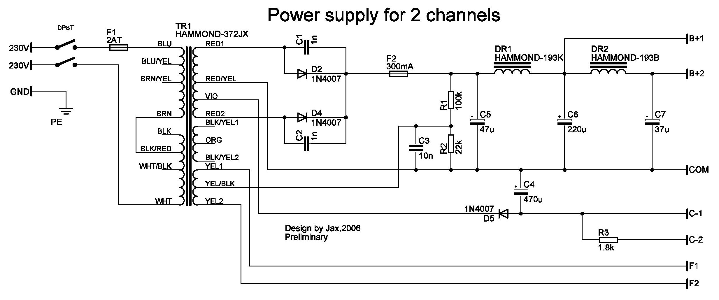
The output stage is changed to fixed bias class AB1. Plate voltage supply is now a single 400V thus simplifying the power supply.
Note that R102 is a trimmer so the current can be adjusted.
Not too complicated to build. Easy to adjust despite as many as 4 trimmers. At least it's easy if you have 2 multimeters.